
 Tech - Super Soaker AquaShock Secret Strike Internals .:
Images from iSoaker.com
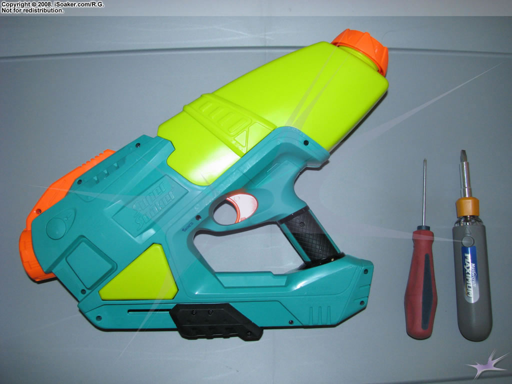 Unopened Super Soaker AquaShock Secret Strike showing side with screw holes. |
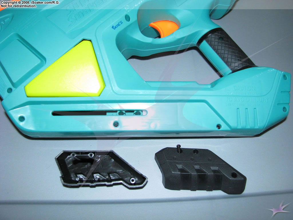 Pump grip held together with three screws. Glip easily split apart once screws were removed.. |
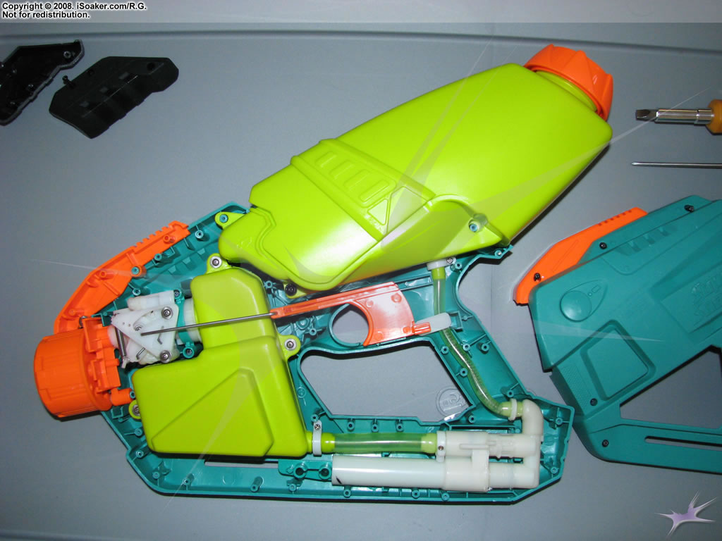 Overview picture of Super Soaker AquaShock Secret Strike internals with side-casing removed. |
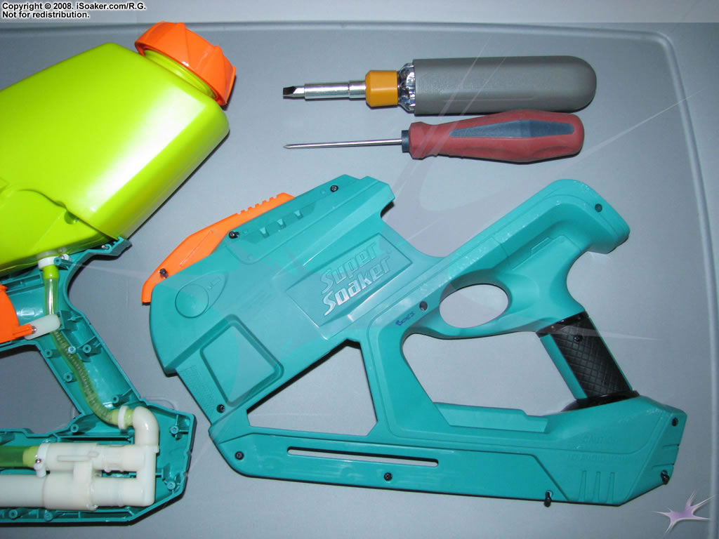 Picture of the left-side casing. |
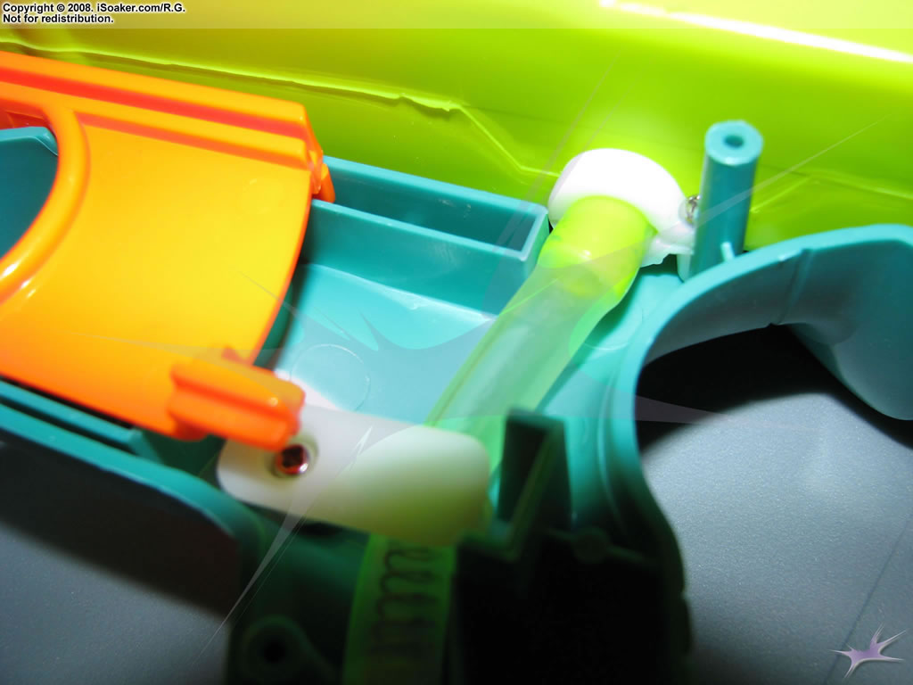
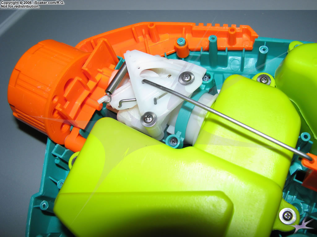
 Close-up of the Max-D trigger system. Trigger rod clearly visible. |
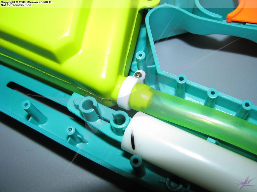
 Close up of reservoir intake tubing. |
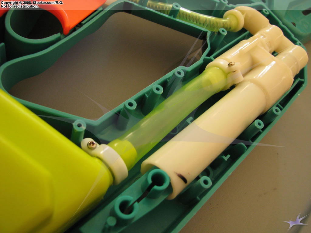
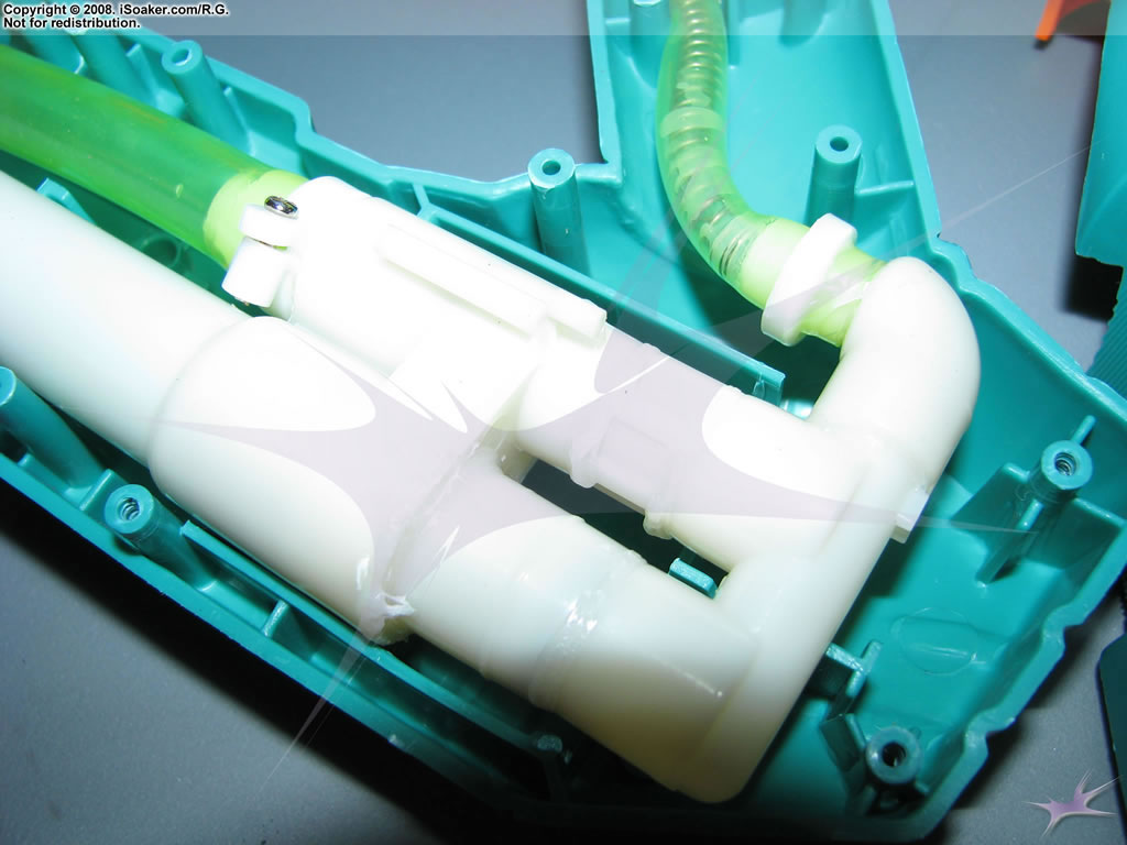 Close up of intake tubing, pump shaft, and check valve assembly. |
 Close up of end of pump shaft as well as input tubing into the pressure chamber. |
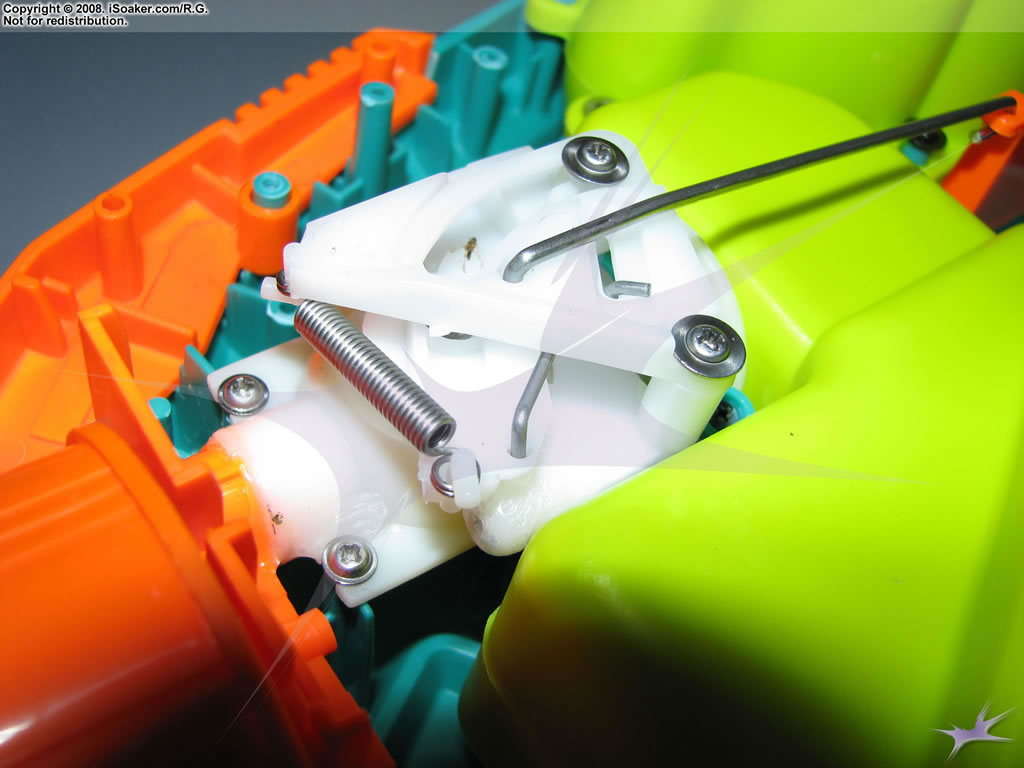
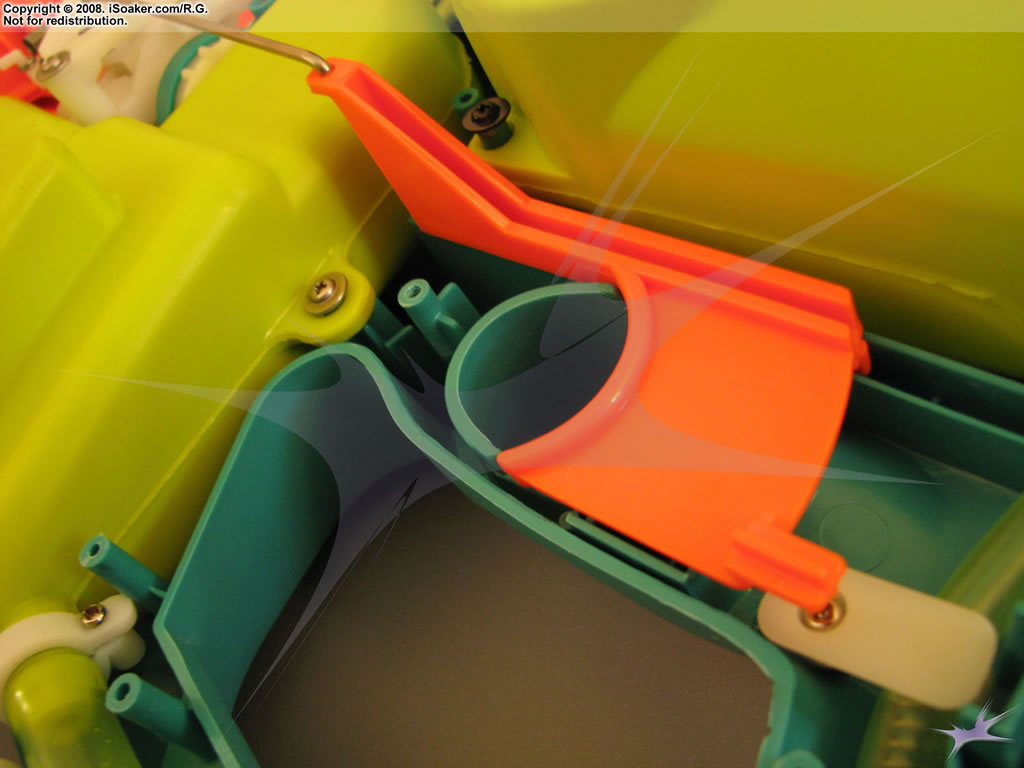
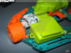
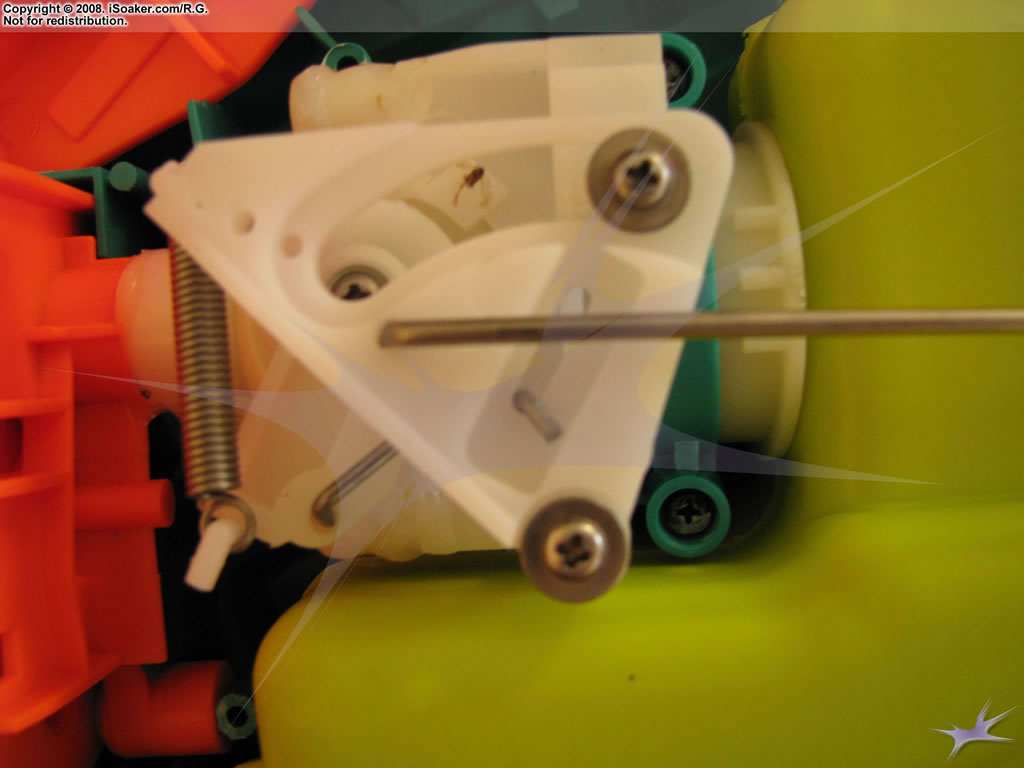 Side view of Max-D nozzle valve mechanism. |
 3/4 view of Max-D nozzle valve mechanism. |
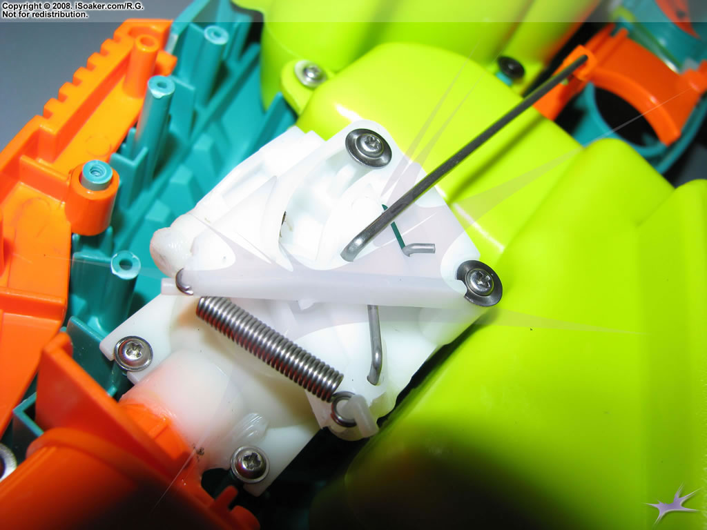
 Zoom out to show nozzle selector and nozzle valve positions. |
 2nd Zoom out to show nozzle selector and nozzle valve positions. |
 3/4 view of pump shaft and tubing assembly. |
 Close up of trigger. Plastic trigger guides clearly visible. |
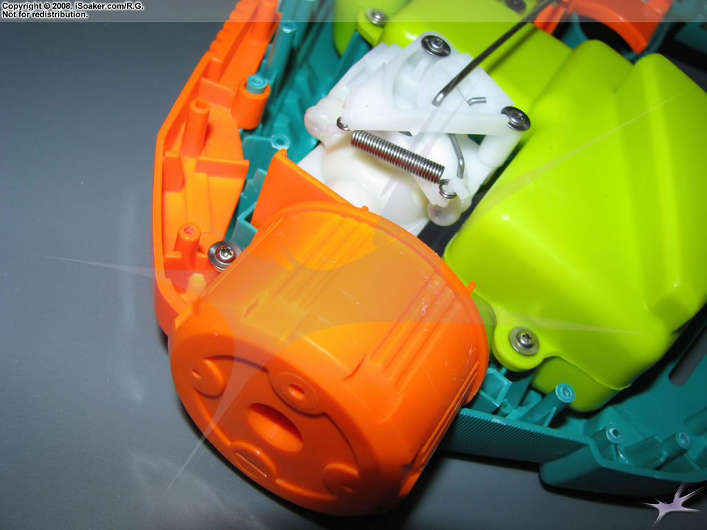
 Alternate view of Max-D valve mechanism and nozzle selector. |
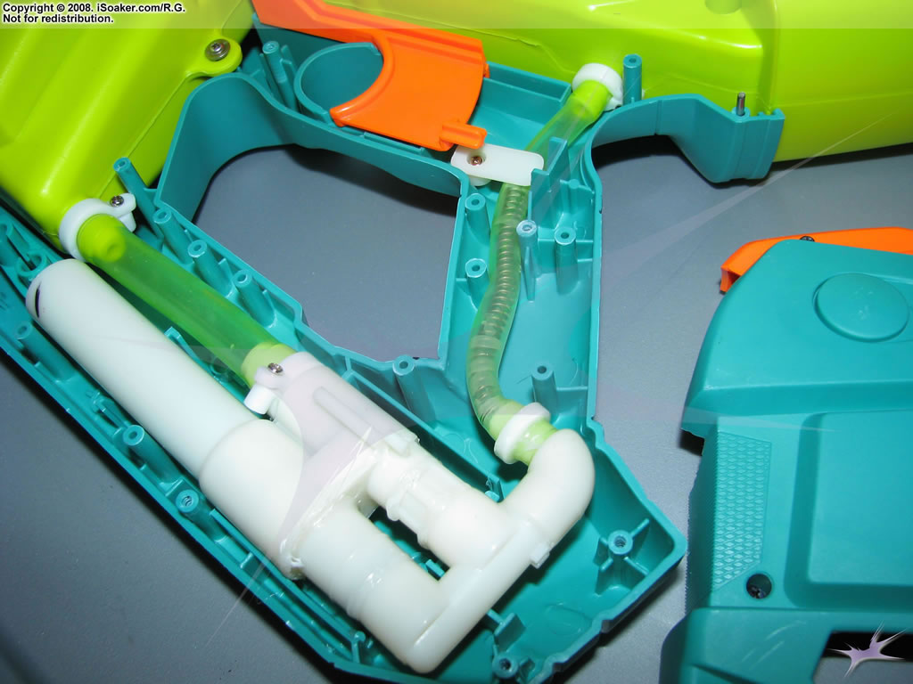 Alternate view of reservoir intake, pump mechanism, and pressure chamber feed line. |
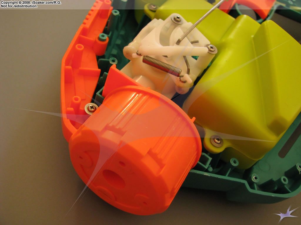
 3/4 picture of pressure chamber to nozzle assembly. |