
 Tech - Super Soaker Quick Blast Internals .:
Images from iSoaker.com
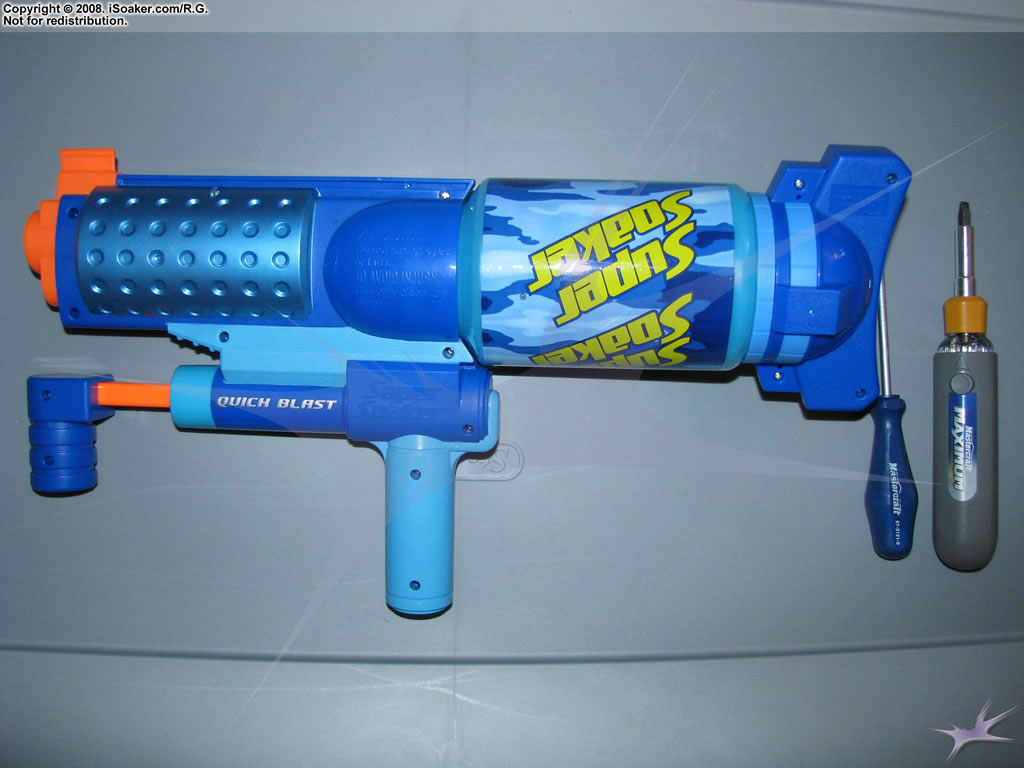 Unopened Liquidator showing the screw holes. |
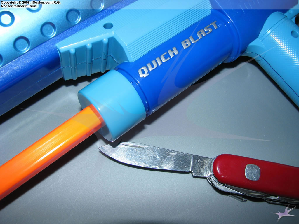 Loosening of the pump-cap. Used a pocket knife to pry the cap loose, popping lightly glued jointss. |
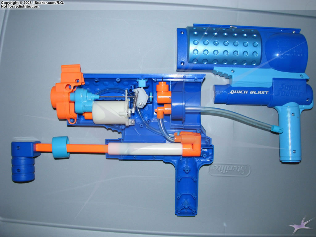 Side case removed. Note: the pump shaft was left attached to the removed casing. |
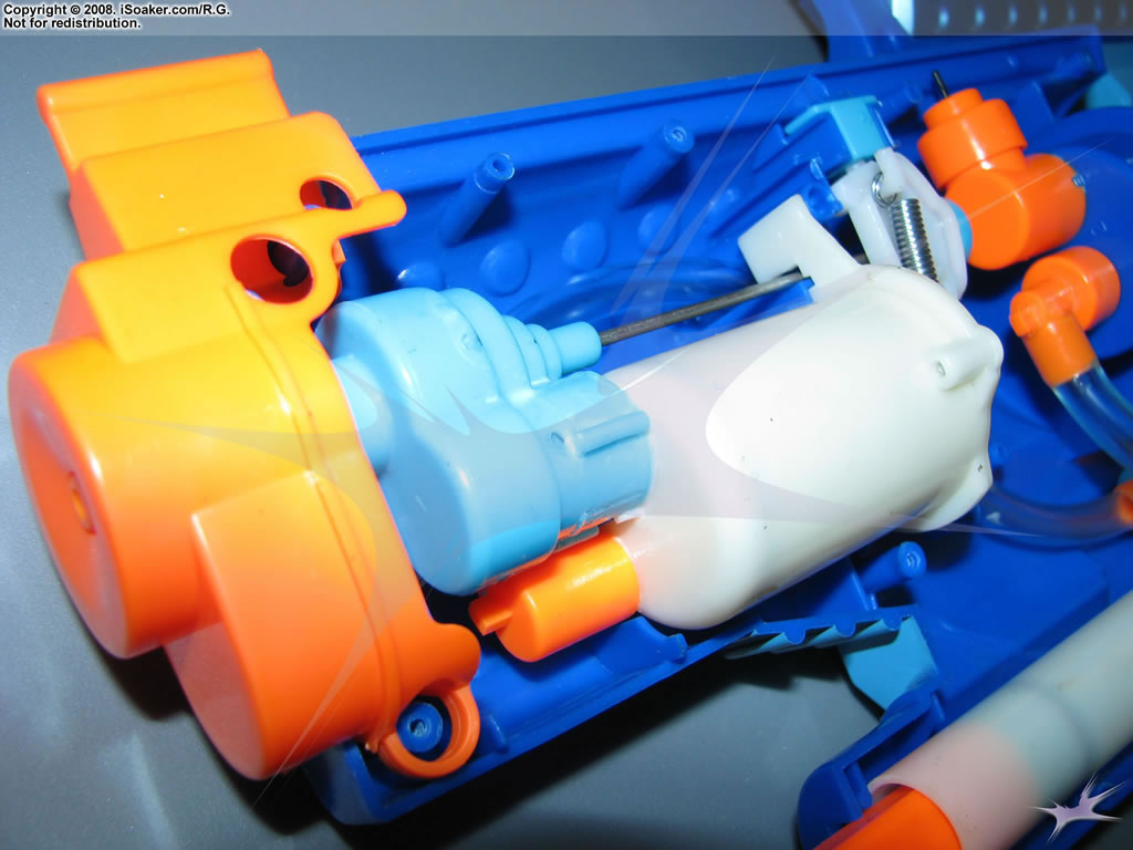
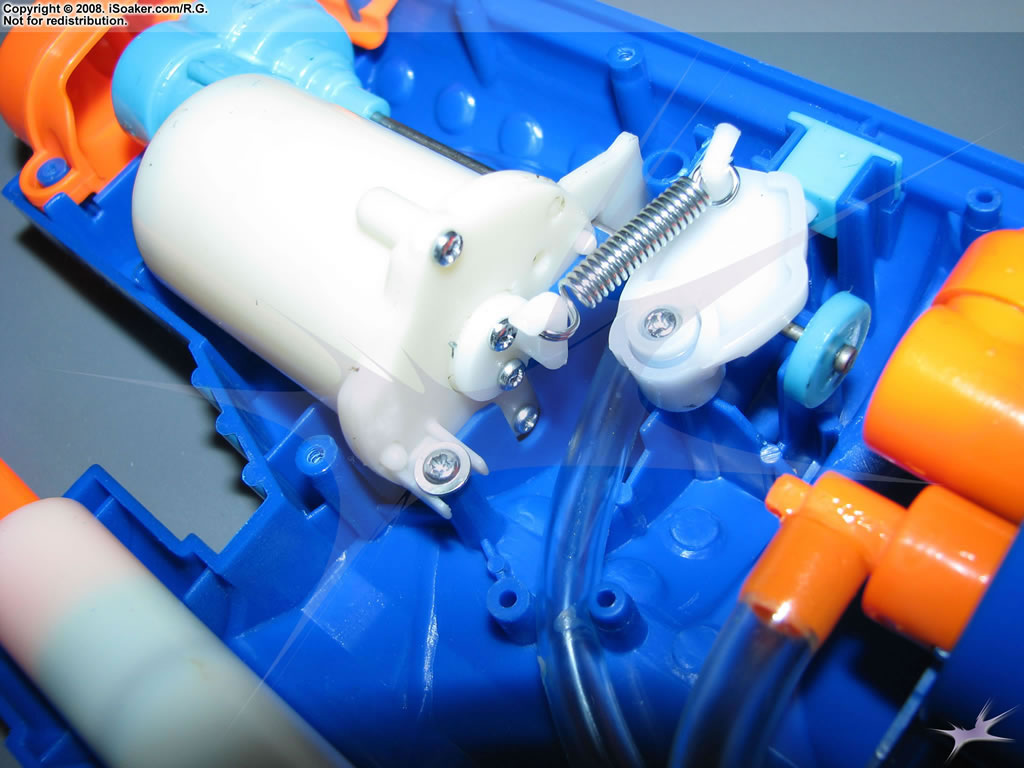 Trigger mechanism and pressure chamber 3/4 rear view. |
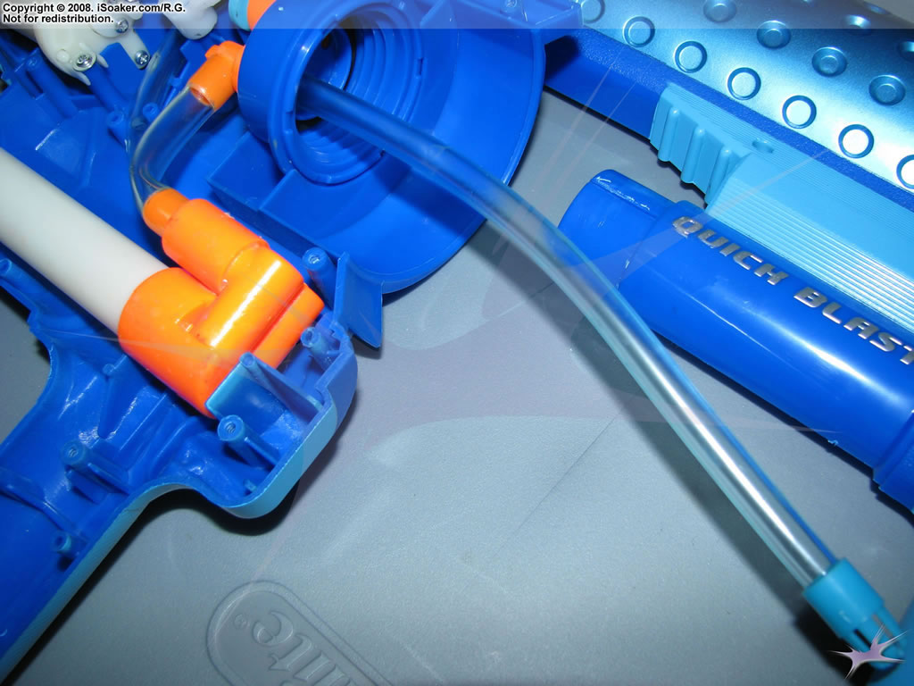 Reservoir intake tubing view. |
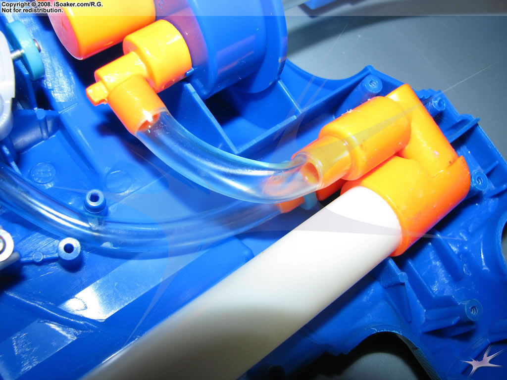 Inner intake tubing to check-valve and pump shaft. |
 Nozzle, pin-valve, and front-section of pressure chamber. |
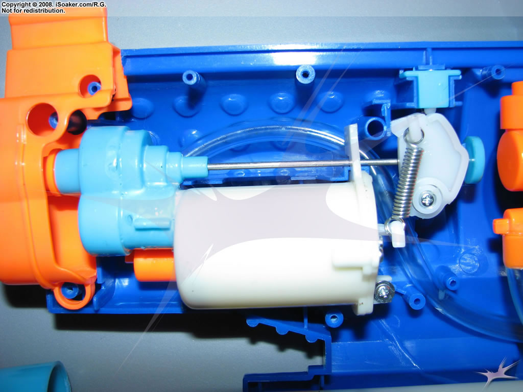 Trigger mechanism and spring-based pressure chamber overview. As PC fills, a piston extends from its back side, pressing against the spring-loaded trigger mechanism that snaps the nozzle valve open when the PC reaches a critical volume. |
 Angled picture of the top of the trigger valve mechanism. Also visible is the air intake for the reservoir. |