
 Tech - Water Warriors Piranha Internals .:
Images from iSoaker.com
Unopened case showing the position of the screw holes. |
 Case only opened partially due to presence of wires from the electronic pressure sensor to the battery case. |
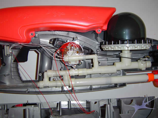 Internal tubing network and CPS-like Hydro-Power diaphragm. |
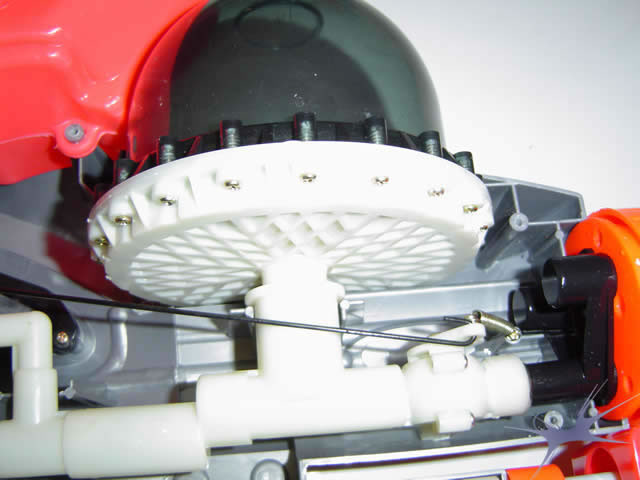 Close-up of the base of the diaphragm pressure chamber. |
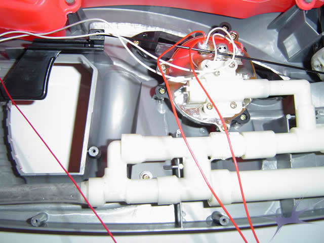 Close-up of the electronic pressure gauge. |
 Alternate view of the electronic pressure gauge and pressure chamber along with the trigger rod and nozzle-valve assembly. |
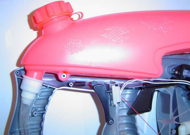 Reservoir intake position and electronic pressure gauge activator switch. |